
Description
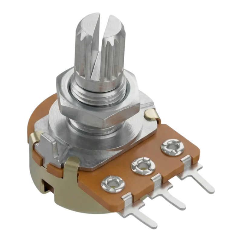
The WH148 panel rotary potentiometer is a passive control element designed for continuous resistance change in electrical and electronic circuits. The 3-terminal design allows use as a voltage divider and as a variable resistor. The product is available in linear characteristic B in several resistance values for installation in devices, control panels and hobby and service applications.
Technical specifications
Product type: rotary potentiometer
Model series: WH148
Design: axial, panel mounting
Number of pins: 3 pins
Characteristics: linear, designation B
Version: mono
Track type: wire
Number of revolutions: 1
Rotation angle: 300°
Nominal resistance values: B1K, B2K, B5K, B10K, B20K, B50K, B100K, B250K, B500K, B1M (depending on variant)
Resistance tolerance: ±20%
Linearity tolerance: ±5%
Power loss Pd: 125 mW
Maximum operating voltage: 200 V
Minimum insulation resistance: 1000 mOhm
Body dimensions: 29x25x17 mm
Shaft length: 13 mm
Shaft diameter: 6 mm
Pin spacing: 5 mm
Mounting hole diameter: 7.2 mm
Fastening: with nut
Functions and features
Manual resistance adjustment by turning the shaft.
The three-terminal connection allows use as a voltage divider.
The linear resistance change is suitable for technical control and adjustment functions.
The axial shaft is designed for mounting in a panel or front plate of the device.
Mechanical fastening with a nut ensures a firm fit in the mounting hole.
The availability of multiple resistance variants makes it easier to choose the appropriate control range.
Ideal for
Signal level regulation in electronic circuits.
Adjustment and control elements in devices and panels.
Kits, prototypes and electronics service repairs.
Simple analog control circuits.
Package contents
1x potentiometer WH148, 3pin
Why choose this product?
Clearly defined linear characteristic B for technical use.
Wide selection of resistance values within one design series.
Compact panel design with standard three-pin connection.
Known mounting dimensions make it easy to design and replace the component.
Installation and operating instructions
Install into a hole of the appropriate diameter and secure the potentiometer with a nut.
When soldering, limit the heating time of the pins to avoid damage to the internal structure.
Before installation, verify the required resistance value and correct connection of the outer and middle terminals.
Observe the maximum operating voltage and power dissipation of the component.
Safety notice
The component is not intended to operate above the specified electrical load limit.
Incorrect wiring may damage the potentiometer or the downstream circuit.
Only perform installation and service when the power supply is disconnected.
When used in equipment connected to hazardous voltages, appropriate structural protection and professional installation must be ensured.
Reviews
There are no reviews yet.